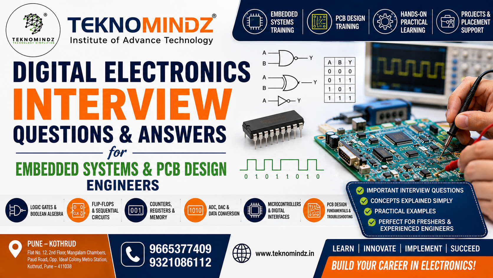
Digital Electronics Interview Questions and Answers for Embedded Systems & PCB Design Engineers in Pune
If you are preparing for an Embedded Systems, PCB Design, Hardware Design, or Electronics Engineering interview, strong knowledge of Digital Electronics is essential. Interviewers often test candidates on digital logic, number systems, logic gates, combinational and sequential circuits, flip-flops, counters, registers, ADC/DAC concepts, microcontrollers, and practical circuit troubleshooting.
For students and freshers attending interviews in Pune's growing electronics and embedded systems industry, preparing these questions can help build confidence and improve technical performance.
Teknomindz Institute of Advance Technology in Kothrud, Pune, focuses on practical training in Embedded Systems, IoT and PCB Designing, including hands-on hardware learning and real-time projects. (teknomindz)
Why Digital Electronics Is Important for Embedded Systems and PCB Design
Digital Electronics forms the foundation of modern embedded products. Microcontrollers, processors, sensors, communication interfaces and digital control circuits all depend on digital logic.
For an Embedded Systems Engineer, concepts such as logic gates, Boolean algebra, flip-flops, timers, counters and digital communication are important for understanding how hardware interacts with firmware.
For a PCB Design Engineer, Digital Electronics knowledge helps in understanding:
-
Digital ICs
-
Power and signal connections
-
Logic-level compatibility
-
Clock circuits
-
Reset circuits
-
Pull-up and pull-down resistors
-
Decoupling capacitors
-
Microcontroller circuits
-
High-speed digital signals
-
PCB signal integrity
This is why Digital Electronics is commonly included in technical interview preparation for electronics and embedded careers.
Top Digital Electronics Interview Questions
1. What is Digital Electronics?
Digital Electronics deals with electronic circuits that process information using discrete signal levels, generally represented by 0 and 1.
Digital circuits are widely used in:
-
Microcontrollers
-
Microprocessors
-
Computers
-
Embedded systems
-
Communication systems
-
Industrial automation
-
Consumer electronics
-
IoT devices
2. What is the difference between Analog and Digital Signals?
Analog signals vary continuously with time, while digital signals have discrete levels.
For example:
Analog:
A temperature sensor may produce a continuously varying voltage.
Digital:
A microcontroller may interpret a signal as HIGH or LOW.
| Analog | Digital |
|---|---|
| Continuous values | Discrete values |
| More susceptible to noise | Generally better noise immunity |
| Used in audio/sensor signals | Used in processors and digital logic |
| Example: microphone output | Example: UART data |
3. What are Logic Gates?
Logic gates are basic digital circuits that perform logical operations.
The commonly used gates are:
-
AND
-
OR
-
NOT
-
NAND
-
NOR
-
XOR
-
XNOR
Understanding their truth tables is one of the most common requirements in electronics interviews.
4. What is an AND Gate?
An AND gate produces HIGH output only when all inputs are HIGH.
For two inputs:
Y = A × B
| A | B | Y |
|---|---|---|
| 0 | 0 | 0 |
| 0 | 1 | 0 |
| 1 | 0 | 0 |
| 1 | 1 | 1 |
5. What is an OR Gate?
An OR gate produces HIGH when at least one input is HIGH.
Y = A + B
The output is LOW only when all inputs are LOW.
6. What is a NOT Gate?
A NOT gate inverts the input.
Y = NOT A
Therefore:
-
Input 0 → Output 1
-
Input 1 → Output 0
7. What are Universal Gates?
NAND and NOR are called universal gates because any digital logic circuit can be constructed using only NAND gates or only NOR gates.
This is a very common interview question for freshers.
Boolean Algebra Interview Questions
8. What is Boolean Algebra?
Boolean algebra is a mathematical system used to analyze and simplify digital logic circuits.
It uses two primary values:
0 and 1
Important Boolean operators include:
-
AND
-
OR
-
NOT
Boolean simplification is useful when designing efficient digital circuits and reducing the number of gates required.
9. What is De Morgan's Theorem?
There are two important De Morgan's laws:
(A · B)' = A' + B'
and
(A + B)' = A' · B'
Interviewers may ask candidates to explain these laws using logic gates.
10. What is a Truth Table?
A truth table shows the output of a digital circuit for every possible combination of input values.
For example, a two-input logic circuit has:
2² = 4 possible combinations.
A three-input circuit has:
2³ = 8 combinations.
Number System Interview Questions
11. What are the Common Number Systems Used in Digital Electronics?
The major number systems are:
-
Binary
-
Decimal
-
Octal
-
Hexadecimal
Digital systems primarily use binary, because digital circuits generally operate using two logical states.
12. Why is Binary Used in Digital Electronics?
Binary uses only two values:
0 and 1
These can conveniently represent two electrical states such as:
-
LOW / HIGH
-
OFF / ON
-
FALSE / TRUE
This makes binary suitable for digital electronic circuits.
13. What is Hexadecimal?
Hexadecimal is a base-16 number system.
It uses:
0–9 and A–F
One hexadecimal digit represents four binary bits.
For example:
F = 1111
Hexadecimal notation is frequently used when working with microcontroller registers, memory addresses and embedded firmware.
Combinational Circuit Questions
14. What is a Combinational Circuit?
A combinational circuit produces an output based only on its present inputs.
It does not store previous input information.
Examples include:
-
Adders
-
Subtractors
-
Multiplexers
-
Demultiplexers
-
Encoders
-
Decoders
15. What is a Multiplexer?
A multiplexer, or MUX, selects one input from multiple inputs and sends it to a single output.
It is commonly called a:
Data Selector
For example, a 4:1 multiplexer has:
-
4 data inputs
-
2 selection lines
-
1 output
16. What is a Demultiplexer?
A demultiplexer performs the opposite function.
It takes one input and routes it to one of several outputs based on the selection lines.
17. What is a Decoder?
A decoder converts coded input information into one of several output lines.
For example, a 2-to-4 decoder has:
-
2 input lines
-
4 output lines
Only one output is normally selected for each input combination.
18. What is an Encoder?
An encoder performs the reverse operation of a decoder.
It converts multiple input lines into a coded output.
A common example is a priority encoder.
Adder Interview Questions
19. What is a Half Adder?
A Half Adder adds two one-bit binary numbers.
It produces:
-
Sum
-
Carry
The equations are:
Sum = A XOR B
Carry = A AND B
20. What is a Full Adder?
A Full Adder adds three inputs:
-
A
-
B
-
Carry-in
It produces:
-
Sum
-
Carry-out
Full adders can be cascaded to create multi-bit binary adders.
Sequential Circuit Questions
21. What is a Sequential Circuit?
Unlike a combinational circuit, a sequential circuit depends on:
Present input + previous state
Therefore, sequential circuits contain memory elements.
Examples include:
-
Flip-flops
-
Registers
-
Counters
22. What is a Flip-Flop?
A flip-flop is a basic memory element capable of storing one bit of information.
Common types are:
-
SR Flip-Flop
-
JK Flip-Flop
-
D Flip-Flop
-
T Flip-Flop
23. What is a D Flip-Flop?
A D Flip-Flop stores the value present at its D input when the appropriate clock edge occurs.
It is widely used in:
-
Registers
-
Data storage
-
Synchronization circuits
-
Digital systems
24. What is a JK Flip-Flop?
A JK Flip-Flop is an improved version of the SR Flip-Flop.
Its important behavior is:
-
J=0, K=0 → No change
-
J=0, K=1 → Reset
-
J=1, K=0 → Set
-
J=1, K=1 → Toggle
25. What is a T Flip-Flop?
A T Flip-Flop toggles its output when the T input is HIGH.
It is commonly used in counter circuits.
Clock and Timing Questions
26. What is a Clock Signal?
A clock is a periodic digital signal used to synchronize operations in digital systems.
Microcontrollers, processors, counters and many synchronous circuits depend on clock signals.
27. What is Frequency?
Frequency represents the number of cycles occurring per second.
The unit is:
Hertz (Hz)
For example:
1 MHz = 1,000,000 cycles per second
28. What is Duty Cycle?
Duty cycle represents the percentage of one period during which a signal remains HIGH.
Duty Cycle = HIGH Time / Total Period × 100
For a symmetrical square wave, the duty cycle is generally 50%.
29. What is Propagation Delay?
Propagation delay is the time required for a change at the input of a digital circuit to appear at its output.
This becomes particularly important in high-speed digital systems and PCB design.
30. What are Setup Time and Hold Time?
These are important timing parameters for flip-flops and other synchronous circuits.
Setup time:
The minimum time the data must be stable before the clock edge.
Hold time:
The minimum time the data must remain stable after the clock edge.
Timing violations can cause unreliable digital operation.
Counter and Register Questions
31. What is a Counter?
A counter is a sequential circuit that goes through a predefined sequence of states according to clock pulses.
Counters are used in:
-
Timers
-
Frequency measurement
-
Digital clocks
-
Event counting
-
Embedded applications
32. What is a Register?
A register is a group of flip-flops used to store multiple bits of data.
For example:
A 8-bit register can store 8 bits.
Registers are extremely important in microcontrollers because configuration and control information is commonly stored in registers.
33. What is a Shift Register?
A shift register stores data and shifts it left or right depending on the circuit configuration.
Applications include:
-
Serial-to-parallel conversion
-
Parallel-to-serial conversion
-
Temporary data storage
-
Communication interfaces
Practical Embedded Systems Questions
34. What is a Microcontroller?
A microcontroller is an integrated circuit containing components such as:
-
CPU
-
Memory
-
GPIO
-
Timers
-
Communication peripherals
It is designed to control electronic systems.
Examples include:
-
8051
-
AVR
-
PIC
-
STM32
-
ESP32
35. What is GPIO?
GPIO stands for:
General Purpose Input/Output
A GPIO pin can generally be configured as an input or output depending on the application.
For example, a microcontroller GPIO can be used to:
-
Read a switch
-
Control an LED
-
Interface with sensors
-
Control a relay
36. What is Pull-Up and Pull-Down?
A pull-up resistor connects a digital input to a positive supply, while a pull-down resistor connects it to ground.
They help prevent a digital input from floating when no active signal is being applied.
This is particularly important when designing microcontroller and PCB circuits.
37. What is a Floating Input?
A floating input is a digital input that is not properly connected to a defined logic HIGH or LOW state.
It can randomly change because of noise or interference.
A pull-up or pull-down resistor can be used to establish a known default state.
ADC and DAC Interview Questions
38. What is an ADC?
ADC stands for:
Analog-to-Digital Converter
It converts an analog voltage into a digital value that a microcontroller or processor can understand.
For example:
Temperature sensor → Analog voltage → ADC → Digital value → Microcontroller
39. What is a DAC?
DAC stands for:
Digital-to-Analog Converter
It converts digital data into an analog signal.
DACs are used in applications such as:
-
Audio systems
-
Signal generation
-
Industrial control
-
Instrumentation
40. What is ADC Resolution?
ADC resolution represents the number of discrete levels an ADC can distinguish.
For an N-bit ADC:
Number of levels = 2ᴺ
Therefore:
-
8-bit → 256 levels
-
10-bit → 1024 levels
-
12-bit → 4096 levels
This is an important calculation-based interview question.
PCB Design Interview Questions
41. Why Should an Embedded Engineer Understand PCB Design?
Embedded engineers often work closely with hardware.
Understanding PCB design helps engineers troubleshoot:
-
Power problems
-
Signal problems
-
Component connections
-
Communication failures
-
Grounding issues
-
Hardware interface problems
For a PCB Design Engineer, Digital Electronics knowledge is even more fundamental.
Teknomindz's PCB Design training includes practical areas such as schematic design, PCB layout, multilayer design, high-speed PCB design, BGA routing and manufacturing file generation. (teknomindz)
42. What is a Schematic?
A schematic is a logical representation of an electronic circuit.
It shows:
-
Components
-
Connections
-
Component values
-
Net names
-
Power connections
The schematic is generally created before PCB layout.
43. What is PCB Layout?
PCB layout is the process of physically arranging components and routing electrical connections on a PCB.
It involves:
-
Component placement
-
Track routing
-
Ground planes
-
Power distribution
-
Design-rule checking
-
Manufacturing preparation
44. What is a Ground Plane?
A ground plane is a large conductive area connected to the circuit's ground.
It can help provide:
-
Low-impedance return paths
-
Better signal integrity
-
Reduced noise
-
Improved EMI performance
-
Better power distribution
45. Why Are Decoupling Capacitors Used?
Decoupling capacitors are commonly placed near IC power pins to help reduce high-frequency supply noise and provide a local source of transient current.
This is a very practical question for Embedded Hardware and PCB Design interviews.
46. What is a Gerber File?
Gerber files are manufacturing data files used by PCB fabrication processes.
They can contain information for layers such as:
-
Copper
-
Solder mask
-
Silkscreen
-
Board outline
Other manufacturing files, such as drill data, may also be required depending on the PCB fabrication process.
47. What is DRC in PCB Design?
DRC stands for:
Design Rule Check
It checks a PCB layout against defined design rules.
Examples include:
-
Minimum track width
-
Minimum clearance
-
Via rules
-
Component spacing
-
Manufacturing constraints
Scenario-Based Interview Questions
These questions are particularly useful for candidates preparing for Embedded Systems and PCB Design interviews.
48. An LED connected to a microcontroller GPIO is not glowing. How will you troubleshoot it?
A good troubleshooting approach would include:
-
Check the power supply.
-
Check GPIO configuration.
-
Verify GPIO voltage.
-
Check LED polarity.
-
Check the series resistor.
-
Check PCB tracks and solder joints.
-
Check the firmware logic.
-
Measure the signal using a multimeter or oscilloscope.
The important thing is to explain the troubleshooting process rather than simply saying "check the LED."
49. A microcontroller keeps resetting. What could be the reason?
Possible causes include:
-
Unstable power supply
-
Voltage drop
-
Poor grounding
-
Watchdog timer
-
EMI/noise
-
Incorrect reset circuit
-
Software crash
-
Insufficient decoupling
-
PCB layout problems
A good engineer should systematically isolate whether the problem originates in hardware, power, PCB or firmware.
50. UART communication is not working. What will you check?
Check:
-
TX/RX connections
-
Baud rate
-
Data bits
-
Stop bits
-
Parity
-
Ground connection
-
Logic voltage levels
-
Firmware configuration
-
Signal waveform
An oscilloscope or logic analyzer can be very useful for debugging the actual communication signals.
Bonus Digital Electronics Interview Questions
For more advanced preparation, candidates should also prepare answers to:
-
What is the difference between latch and flip-flop?
-
What is metastability?
-
What is clock skew?
-
What is clock jitter?
-
What is fan-in and fan-out?
-
What is noise margin?
-
What is CMOS logic?
-
What is TTL logic?
-
What is the difference between synchronous and asynchronous counters?
-
What is a ring counter?
-
What is a Johnson counter?
-
What is a Schmitt trigger?
-
What is a tri-state buffer?
-
What is a state machine?
-
What is the difference between synchronous and asynchronous reset?
-
What is debouncing?
-
Why is switch debouncing required in embedded systems?
-
What is the difference between active-HIGH and active-LOW signals?
-
What is signal integrity?
-
What is the difference between SPI, I2C and UART?
How to Prepare for a Digital Electronics Interview
Don't prepare these questions only by memorizing definitions. Interviewers for embedded and hardware positions often move from a basic question to a practical problem.
For example:
Interviewer: What is a pull-up resistor?
A candidate should be able to continue with:
Why is it required? → Where is it used? → What happens without it? → How would you select its value?
Similarly:
Interviewer: What is SPI?
You should be prepared to explain:
SCLK → MOSI → MISO → Chip Select → Master/Slave → Full Duplex → Practical application.
This approach is particularly useful for Embedded Systems interviews.
Digital Electronics + Embedded Systems + PCB Design
Candidates aiming for hardware and embedded careers should ideally develop knowledge across three connected areas:
Digital Electronics
Learn:
-
Logic gates
-
Boolean algebra
-
Combinational circuits
-
Sequential circuits
-
Flip-flops
-
Counters
-
Registers
-
ADC/DAC
-
Digital timing
Embedded Systems
Learn:
-
Embedded C
-
Microcontrollers
-
GPIO
-
Timers
-
Interrupts
-
UART
-
SPI
-
I2C
-
CAN
-
Sensors
-
RTOS
-
Debugging
PCB Design
Learn:
-
Circuit schematics
-
Component selection
-
PCB layout
-
Routing
-
Grounding
-
Power distribution
-
Multilayer PCB
-
High-speed design
-
DRC
-
Gerber generation
-
Hardware debugging
This combination gives electronics candidates a stronger foundation for hardware and embedded product development.
Prepare for Embedded & PCB Design Careers with Teknomindz Pune
Teknomindz Systems and Services LLP- Training Institute in Kothrud, Pune provides industry-oriented training in Embedded Systems, IoT and PCB Designing, with practical laboratory learning, development boards, projects and career/placement support. The institute states that its batches are limited to a maximum of eight students for personalized learning. (teknomindz)
Its Pune center is located at Flat No. 12, 2nd Floor, Mangalam Chambers, Paud Road, opposite Ideal Colony Metro Station, Kothrud, Pune – 411038. (teknomindz)
Teknomindz Pune Contact
📞 9665377409 | 9321086112
If you are preparing for an Embedded Systems or PCB Design interview, building strong Digital Electronics fundamentals along with practical hardware experience can make your interview preparation much more effective.
Frequently Asked Questions
Is Digital Electronics important for Embedded Systems interviews?
Yes. Digital Electronics provides the foundation for understanding microcontrollers, digital interfaces, logic circuits, timing, hardware debugging and embedded hardware design.
What Digital Electronics topics should freshers prepare?
Freshers should focus on logic gates, Boolean algebra, number systems, multiplexers, decoders, adders, flip-flops, counters, registers, ADC/DAC, timing concepts and basic microcontroller interfaces.
Is Digital Electronics required for PCB Design jobs?
Yes. Understanding digital circuits helps PCB designers understand schematics, IC connections, power and ground, signal routing, logic levels and hardware interfaces.
What practical questions can be asked in Embedded Systems interviews?
Interviewers may give troubleshooting scenarios involving LEDs, GPIOs, UART communication, power supplies, resets, sensors, communication interfaces and hardware/firmware interaction.
Where can I learn Embedded Systems and PCB Design in Pune?
Teknomindz Institute of Advance Technology offers practical training in Embedded Systems, IoT and Industrial PCB Designing at its Kothrud, Pune center. (teknomindz)